
User Manual for the SOLDROG Controller
1. Intended Use
The controller described in this manual is intended for controlling the SOLDROG machine.
The manufacturer is not responsible for any damages resulting from use that is inconsistent with its intended purpose.
2. Safe Use Guidelines
All safety regulations and instructions must be read. Failure to follow safety guidelines and instructions may result in electric shock, fire, and/or serious bodily injury. All safety regulations and instructions should be kept for future reference. Children should not be allowed near the device’s working area. People with implanted pacemakers should consult their doctor. Service and repairs of the device should only be carried out by qualified personnel, adhering to the safety standards for electrical equipment.
Unauthorized modifications may alter the device’s functionality or worsen its performance. Any unauthorized modifications will not only void the warranty but may also compromise user safety, increasing the risk of electric shock. Improper operating conditions and incorrect handling may damage the device and void the warranty.
3. Contents of the Set
The following items should be included in the set:
- Controller
- Instruction manual
4. Technical Specifications of the Controller
| Wire Color | Value |
|---|---|
| red | 11-16 V |
| black | 2 W |
5. Power Connection of the Controller
| Wire Color | Value |
|---|---|
| red | + 12 V |
| black | - GND |
6. Fuse
The controller is equipped with a protection in the form of an instantaneous 50A fuse (MTA MIDIVAL 50A). Do not use strip fuses.
7. Buttons
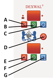
| Description | |
|---|---|
| A | Increase engine speed |
| B | Reduce engine speed |
| C | Rotor on/off. After startup, the rotor will rotate at the level indicated on the display. (Rotation range from 10 to 99) |
| D | Switching on/off the controller. |
| E | Reduce the vibrator start-up interval |
| F | Increase the vibrator start-up interval |
| G | Switching on/off the vibrator. 1. value of 0 - continuous vibration. 2. Value in the range 1-99 - interval between vibrator activations. |
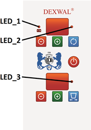
| LED1 | Lights up with continuous light. Power supply voltage of the controller is too low (Uz<10V).The controller may operate unstably. |
| LED1 | Slow flashing. Low supply voltage (10V<Uz<11V). The controller should work correcting. |
| LED1 | Blanked out. Correct supply voltage of the controller (11V<Uz<16.5V). |
| LED1 | Flashing fast. Controller power supply voltage too high (Uz>16.5V). The controller may be damaged. |
| LED2 | Luminous diode indicates that the rotor is running |
| LED3 | A glowing LED indicates that the vibrator is running |
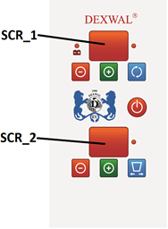
| SCR1 | A glowing LED indicates that the vibrator is running |
| SCR2 | The display indicates the degree of flap opening, with the servo on. |
8. Voltage Measurement
To display the current voltage, simultaneously press and hold buttons A and B (see diagram A) for 2 seconds. The voltage will be displayed on both displays A and B. For example, if display A shows the value 14 and display B shows 40, the voltage is 14.40 V.
9. Alarms
During the operation of the controller, an alarm may occur, caused by, for example, rotor blockage or exceeding the device’s maximum operating temperature. The alarm information will be displayed on the device’s screens and accompanied by an audible signal.
After an alarm occurs, check if the rotor is blocked. Before restarting the controller, wait for approximately 5 minutes.
10. Warnings
After each use of the machine, the salt tank must be thoroughly emptied. Operating the device with a blocked rotor may result in damage to the controller.
11. Safety Button
Safety button a red safety button is located on the controller’s housing. In the event of a malfunction during the operation of the device, the button should be pressed immediately.
12. Starting the Controller
- Check the overall condition of the SALTDROG machine, the controller, control and power cables, and their insulation.
- Check if the rotor disc rotates freely and is not blocked by foreign objects in the salt hopper.
- Connect the two wires that link the controller to the device using the yellow XT60 and XT90 connectors.
- After disconnecting the battery, connect the power wires of the controller to the vehicle’s battery terminals, starting with the red wire (+), which has the fuse, followed by the black wire (ground). Connect the terminals to the battery in exactly the same order. Do not reverse the connection order, as it may cause a short circuit, potentially leading to the battery exploding or even a vehicle fire. The red wire should be connected to the positive (+) terminal, and the black wire to the negative (-) terminal of the battery. Ensure the power wire connections to the battery terminals are secure, as the current flowing through the power circuit can be as high as several dozen amperes. A poor connection between the power wires and the battery terminals can cause significant voltage drops, leading to increased temperatures at these connections during operation. This, in turn, may result in improper operation of the controller.
- After verifying the correct connection of the power and control wires, the controller can be started by turning the mushroom safety switch slightly to the left. The safety mushroom switch must be in the off position (the switch lever is not pressed).
- Turn on the controller using the on/off button (D).
- To start operation, turn on the salt spreading motor using button (C) and set its SPEED. If necessary, use the vibrator option.
- To turn off the controller, press button (D), which will switch the controller to standby mode. The complete power disconnection of the controller can be done using the safety switch. For longer periods of inactivity, turn off the controller with the safety switch or disconnect it completely from the power source, and protect the controller from bad weather conditions.
AFTER COMPLETING OPERATION, THE SALT HOPPER MUST BE CHECKED WITHOUT FAIL. LEAVING SALT IN THE HOPPER IS PROHIBITED. HARDENED SALT CAN CAUSE COMPLETE DAMAGE TO THE MACHINE, MOTOR, AND CONTROLLER. WORKING WITH A BLOCKED SPREADING DISC CAN LEAD TO A VEHICLE FIRE.
If the controller cannot be started, check if the fuse in the power supply cable is functional and if the safety switch is not pressed.
13. Cleaning and Maintenance
The protection rating of this device is IP 51. When planning maintenance, the intensity and operating conditions should be taken into account. Proper use of the device and regular maintenance will help avoid unnecessary disruptions and downtime. All maintenance tasks should be performed after disconnecting the device from the power supply.
14. Storage
The device should be stored in a dry, well-ventilated area, out of reach of children. It is recommended to store the device clean.
15. Warranty
The manufacturer provides full warranty and post-warranty service for the device.
The device is secured with two safety seals. Removal or destruction of the seals results in the loss of the warranty.