
SOLDROG PRO
1. Intended Use
The controller described in this manual is designed to operate the Saltdrog or Zefir machine. The manufacturer is not liable for any damages resulting from improper use contrary to its intended purpose.
2. Safe Usage Guidelines
It is essential to read the necessary safety regulations and all provided instructions. Failure to comply with safety regulations and instructions may result in electric shock, fire, and/or serious personal injury. All safety regulations and the instruction manual should be kept for future reference. Children must not be allowed near the device’s operating area. Individuals with pacemakers should consult their doctor.
Servicing and repairs of the device may only be carried out by qualified personnel while adhering to the safety standards applicable to electrical devices. Unauthorized modifications to the device may alter its functional properties or impair its performance. Any structural changes made independently not only void the warranty but may also compromise user safety, exposing the operator to the risk of fire or electric shock. Improper working conditions and misuse may result in device damage and loss of warranty.
3. Package Contents
The following items should be included in the package:
– Control station
– Power cables
– Remote control
– User manual
4. Technical Specifications
| Name | Value |
|---|---|
| Power Supply Voltage | 11-16V |
| Minimum Power Consumption | 2W |
| Fuse | 50A |
5. Remote Control Description
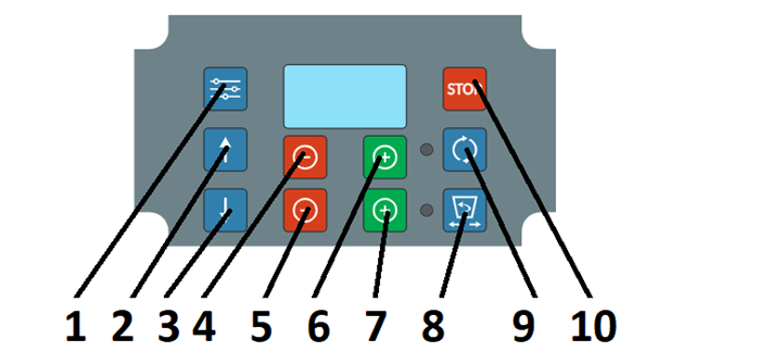
5.1. Description of Remote Control Buttons
| Settings | Work | |
|---|---|---|
| 1 | Menu | Menu, Confirmation |
| 2 | Parameters | Move Up in Menu |
| 3 | Decrease Rotor Speed | Move Down in Menu |
| 4 | Decrease Rotor Speed | Change Value and Menu Parameters |
| 5 | Decrease vibrator start intervals / servo position | Decrease Vibrator Start Intervals / Servo Position |
| 6 | Increase rotor speed | Change Values and Menu Parameters |
| 7 | Increase vibrator start intervals / servo position | Changing the Values and Parameters in the Menu |
| 8 | Open dosing valve (back in menu, parameters) | Back (Previous) in Menu |
| 9 | Start Rotor | Confirm in Menu |
| 10 | Stop | Stop |
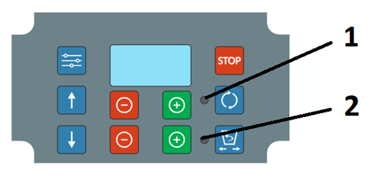
5.1. Description of Remote Control LED
| Description | |
|---|---|
| 1 | The illuminated green LED indicates that the disc spreader motor is currently running. |
| 2 | The illuminated green LED indicates that the vibrator is currently running. |
6. First Start-Up
Before starting the device, check the power supply voltage and the condition of the power cables connected to the controller. The power supply voltage parameters are provided in the technical specifications section of this manual. Any damage to the device’s cables or their insulation renders the device unusable. The start-up should be carried out according to the following steps:
6.1. Connecting the Control Station
Connect the control station to the machine using the XT60 and XT90 connectors. Then, connect the power supply. The red wire should be connected to the positive (+) terminal, and the black wire to the negative (-) terminal of the battery.
If the device is incorrectly connected to the machine, the remote control will display an error message (see the “Error Information” section).
A flashing button on the control station indicates that the station is ready to pair with the remote control.
6.2. Starting the Remote Control
Remote Control Version A (power button located on the top of the housing) – Turn on the remote control using the button located on the top of the housing.
Remote Control Version B (no power button on the top of the housing) – Press and hold the STOP button for 3 seconds.
6.3. Automatic Pairing
- After activation, the remote control automatically detects the previously paired control station and establishes a connection. A steadily lit button on the control station indicates that the remote control has been successfully connected.
- Automatic pairing of the remote control with the central unit occurs only when the “Start-Up” option is enabled in the settings.
- During the waiting period for the connection, it is not possible to manually exit the pairing mode. You must wait for the pairing process to complete. If the connection is not established, the device will enter MENU mode.
6.4. Manual Pairing
- To manually pair the remote control, go to the menu mode, navigate to the device section, search for the station you want to connect to, select it, and confirm. Once the connection is successful, the device will display the operation menu and be ready for control..
- If the connection attempt fails, ensure that you are within the range of the control station, that the control station is properly connected, and that the status indicator button on the station is flashing red. Then, repeat step 7.4 a).
6.5. Turning Off the Device
- Remote Control Version A – To turn off the remote control, press the button located on the top of the housing to the 0 position. The device can also be turned off in the same way as described for Remote Control Version B.
- Remote Control Version B – To turn off the remote control, press and hold the STOP button for approximately 4 seconds. A countdown will appear on the display indicating the time remaining until the remote control is turned off. The device will be powered off. After pressing and holding the STOP button again for about 3 seconds, the device will be ready to operate once more.
7. Error Information.
7.1. Vibrator Not Connected
The controller automatically detects if the vibrator is not connected. In the event of an issue with the vibrator motor connection, the controller will display a message on the screen. After resolving the issue, the message should be confirmed by pressing any button.
7.2. Motor Not Connected
The controller automatically detects if the main motor of the device is not connected. In the event of an issue with the motor connection, the controller will display a message on the screen. After resolving the issue, the message should be confirmed by pressing any button.
7.3. Incorrect Power Supply Voltage
The controller automatically detects incorrect power supply voltage. If there are any power-related errors, the remote control will display a message on the screen. After resolving the power issue, the message should be confirmed by pressing any button.
7.4. Main Motor Blocked
The controller automatically detects a blocked main motor. If an error related to the blocked motor occurs, the device will automatically shut down the machine and display an error message on the screen. The blocked motor should be unblocked by removing any foreign objects or accumulated clumps of salt. After resolving the issue, the message should be confirmed by pressing any button, and then operation can continue.
7.5. Vibrator Motor Blocked
The controller automatically detects if the vibrator motor is blocked. If an error occurs related to the blocked vibrator motor, the device will automatically shut down the machine and display an error message on the screen. The blocked motor should be unblocked by removing any foreign objects or accumulated clumps of salt. After resolving the issue, the message should be confirmed by pressing any button, and operation can continue.
7.6. Battery Discharged
The controller will display a message indicating that the battery is discharged. The device’s battery should be connected and recharged before continuing operation..
7.7. Connection Error
The controller is unable to connect to the control unit. Ensure that the control unit is properly connected to the power supply, the power switch of the control unit is pressed, and the LED on the power switch is flashing. The remote control and control unit must be within range. Attempt to reconnect. If the connection fails, turn off the remote control, power off the control unit, wait at least 10 seconds, and then power the control unit back on. When the LED on the control unit button starts flashing, turn on the remote control or pair the device again.
7.8. Connection Lost with Server
Make sure that the control unit is turned on, move closer to the control unit, and restart the remote control to automatically reconnect with the control unit.
7.9. High Temperature
The controller monitors the current operating temperature of the control unit. If the allowed temperature limit is exceeded, the controller will stop the machine’s operation. A temperature warning message will appear on the remote control display. The temperature may exceed the limit due to prolonged operation of the device or blocked motors in the machine.
7.10. Vehicle Battery Protection
The controller monitors the current voltage of the vehicle’s battery. The battery status is displayed as an icon on the screen. A flashing battery icon indicates an issue with the vehicle’s battery or charging system. To protect the battery from complete discharge, check the battery condition and the vehicle’s charging level.
8. Charging and Remote Control Battery
- When the battery of the remote control is low, it should be charged using a USB Type-C cable (see Fig. 3 for the location of the charging port). Battery status is displayed in the upper-right corner of the screen. It is acceptable to charge the battery at any time. Installing a USB charger in the vehicle allows the device to be charged continuously during operation.
- Charging Time: The charging time depends on the battery’s discharge level. The time required to charge the battery from 0% to 100% is a minimum of 4 hours, depending on environmental temperature and charger specifications. Once fully charged, the display will show a “FULL” icon in the upper-right corner. The battery will be maintained at full charge after it reaches 100%.
- Required Charger Specifications:
- Output voltage: 5V (max)
- Current output: 1A (min) Using a charger that does not meet these specifications may cause damage to the device and void the warranty.
- Long-Term Storage: If the device will not be used for an extended period, the battery should be fully charged. After charging, turn off the device according to the instructions and store it in a dry, safe place. At least once a year, the battery should be charged to full capacity.
- Low Battery Warning: When the battery level drops to 10%, the battery icon on the display will start to blink, indicating that charging is required. If the battery is fully discharged, the display will show the low battery message, and the machine’s motors will be turned off. The device will automatically shut down. The device will become operational again only after being connected to a charger.
- Energy Saving: If the device is idle for a certain period, the remote control will automatically turn off after 30 minutes by default. This period can be adjusted in the settings under the “Turn off after” tab. The idle time is measured from when the motors stop running, and the green LEDs turn off. Once the set idle time is reached, the remote control will turn off. To turn the remote back on, press and hold the STOP button, or follow any other available method for turning the device on as per the instructions.
- Charging Port Maintenance: Ensure that the charging port remains clean. Harsh weather conditions, excessive dust, or dirt can contaminate the charging port and may cause permanent damage. For prolonged use, it is recommended to use charging cables while the device is in use or to cover the port with caps when not in use.
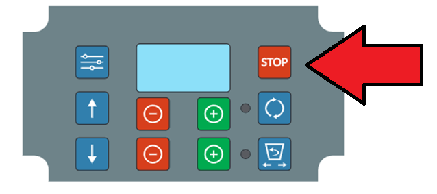
9. STOP
If, during the operation of the device, we want to immediately stop the machine, the STOP button (Fig. 4) should be pressed. The machine’s operation is suspended, and changing modes and work parameters is not possible. Flashing red LEDs (1) and (2) indicate that the controller is in STOP mode. The STOP message appears on the display. Pressing the button again disables the STOP function. To restart and continue the machine’s operation, the STOP function must be disabled, and the button (9) should be pressed.
10. Language selection.
You need to enter the menu, select the “Settings” tab, and then choose “Languages”.
11. Device parameters.
To check the device parameters, such as supply voltage, control center temperature, connection status, and current range, go to the “Parameters” tab. The displayed parameters are the current settings of the device’s control center. During operation, press and hold button (2). The “Silo” parameter is available upon request, with a level sensor for monitoring the current fill level of the tank..
12. Disc spreading speed.
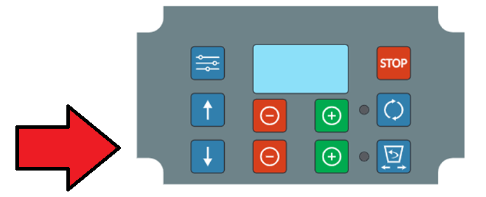
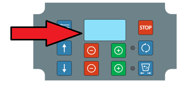
To decrease the motor speed, press button (4); to increase the speed, press button (6). The green LED (1) indicates that the disc spreading motor is turned on. The motor can be turned on or off by pressing button (9). After pressing button (9) to turn on the motor, the vibrator motor will automatically turn on after 2 seconds. In the case of the Zefir machine, the dosing nozzle will open. The red arrow (Fig. 5) indicates the location of the information about the current speed level.
13. Vibrator anti-suspension / dosing nozzle operation interval.
To increase or decrease the time the vibrator will be active, press button (7) or button (5). The display will show the percentage of the vibrator’s operating time during the cycle. The cycle duration can be changed in the settings from 3 to 180 seconds. After changing this parameter, the remote must be restarted. For example, if the cycle is set to 10 seconds and the percentage setting is 40%, it means the vibrator will operate for 4 seconds, then turn off for 6 seconds, and so on, alternating between 4 seconds of operation and 6 seconds of rest. If the vibrator is set to 10% with a 10-second cycle, it will run for 1 second and then rest for 9 seconds. The green LED (2) indicates that the vibrator is operating. The red arrow (Fig. 5) shows the location of the current speed level information. Similarly, for the Zefir machine, the dosing nozzle slide is adjusted with buttons (5) and (7). Full closure or opening is controlled by button (8).
14. Tank content level. Function available upon request.
The sensor should be installed in the upper part of the hopper, and then connected to the socket on the control unit. Once the sensor is detected, the percentage of the current fill level of the tank will be displayed in the engine window. The sensor must be calibrated in the settings by measuring and entering the height of the tank. A low medium level in the hopper will be indicated by a message along with an audible signal. By default, the device control unit is not equipped with a level sensor socket.
15. Configuration
In the “Settings” menu section, we can change the device parameters:
- Startup – Immediately after turning on the remote, it automatically searches for and connects to the previously paired control station. Disabling this will cause the remote to go directly to the MENU section upon startup, and the connection will be established by confirming the START tab in the MENU.
- Brightness – Adjust the brightness of the indicator LEDs.
- Sound – Turn the device sound on or off.
- Language – Select the language and confirm with the approval button.
- Turn off after – Idle time after which the remote will automatically turn off.
- Motor error – Always set to “On.” Turning this off may damage the controller.
- Vibrator error – Always set to “On.” Turning this off may damage the controller.
- Period – Adjust the vibrator operating cycle. Default is set to 10 seconds. This parameter is related to the percentage work time indicator of the vibrator. It defines the maximum break time for the vibrator’s operation. Available after connecting to the SALTDROG machine.
- Motor error correction – Default set to value 50. Increase the value by 10 if motor errors occur too frequently.
- Servo closed – Calibration of the dosing valve in the closed position. Adjust if the valve does not close properly or if the closed valve moves too far. Default value is 50. Available after connecting to the ZEFIR machine.
- Servo open – Calibration of the dosing valve in the open position. Adjust if the valve is not fully open or if the valve opening exceeds the regulation range. If you hear concerning noises from the servo mechanism, adjust this value. Default value is 50. Available after connecting to the ZEFIR machine.
- Tank height – Measure and set the tank content height at which a low level warning will be triggered. This function is only available with the tank level sensor. Available with the sensor upon request.
16. Storage
The device should be stored in a dry, well-ventilated area, out of reach of children. It is recommended to store the device cleaned.
17. Warranty
The manufacturer provides full warranty and post-warranty service.
The device is secured with two safety seals. Removal or destruction of the seals will result in the loss of the warranty.