
Operating instructions of the ZEFIR controller
1. Intended use
The controller described in this manual is intended for controlling the Zefir machine.
The manufacturer is not responsible for any damages resulting from improper use.
2. Safe Use Guidelines
All safety regulations and instructions must be read. Failure to comply with health and safety regulations and instructions may result in electric shock, fire, and/or serious bodily injury. All safety regulations and instructions should be kept for future reference. Children must not be allowed near the device’s work area. People with a pacemaker should consult their doctor. Service and repair of the device should be carried out by qualified personnel, observing the safety conditions applicable to electrical devices.
Modifications made independently may alter the device’s functionality or degrade its performance. Any modifications made independently not only void the warranty but may also compromise user safety, exposing the user to the risk of electric shock. Improper working conditions and improper handling may cause damage to the device and void the warranty.
3. Contents of the Set
The following items should be included in the set:
- Controller
- Manual
4. Technical Specifications of the Controller
| Nazwa | Wartość |
|---|---|
| Napięcie Zasilania | 11-16 V |
| Min pobór mocy | 2 W |
| Bezpiecznik | 10 A |
5. Power Connection of the Controller
| Kolor przewodu | Table header |
|---|---|
| czerwony | 11-16 V |
| czarny | 2 W |
| Kolor przewodu | Opis |
|---|---|
| Zielony + Niebieski | +12V Silnik Główny/ +12V Main Motor |
| Czarny + Brązowy | Masa Silnika Głównego |
| Biały | Masa Serwo |
| Żółty | Sygnał Serwo |
| Czerwony | +5 Serwo |
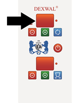
6. Buttons
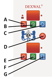
| Nr | Opis |
|---|---|
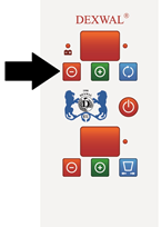
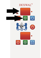
| A | Zwiększenie obrotów silnika |
| B | Zmniejszenie obrotów silnika |
| C | Włączania/wyłączania silnika. Po uruchomieniu silnik będzie obracać się na poziomie wskazanym na wyświetlaczu. |
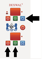
| D | Włączenie/wyłączenie sterownika. |
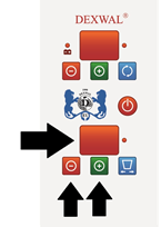
| E | Zwiększenie kąta otwarcia dyszy dozującej. |
| F | Zmniejszenie kąta otwarcia dyszy dozującej. |
| G | Służy do włączania/wyłączaniu serwomechanizmu. Po uruchomieniu przepustnica będzie otwarta na poziomie wskazanym na wyświetlaczu. |
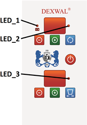
| LED1 | Świeci światłem ciągłym. Zbyt niskie napięcie zasilania sterownika (Uz<10V).Sterownik może pracować niestabilnie. |
| LED1 | Miga wolno. Niskie napięcie zasilania (10V<Uz<11V). Sterownik powinien działać poprawianie. |
| LED1 | Wygaszona. Prawidłowe napięcie zasilania sterownika (11V<Uz<16,5V). |
| LED1 | Miga szybko. Zbyt wysokie napięcie zasilania sterownika (Uz>16,5V). Sterownik może ulec uszkodzeniu. |
| LED2 | Świecąca dioda informuje o uruchomionym wirniku |
| LED3 | Świecąca dioda informuje o otwarciu przepustnicy dozującej ziarno. |
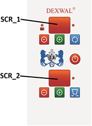
| SCR1 | Wyświetlacz wskazuję stopień obrotów talerza, przy włączanym silniku. |
| SCR2 | Wyświetlacz wskazuję stopień otwarcia klapy, przy włączonym serwomechanizmie. |
7. Voltage Measurement
To display the current supply voltage, press and hold buttons A and B simultaneously. The total value will be shown on the SCR_1 display, and the decimal value will be displayed on SCR_2. For example, if the SCR_1 display shows 14 and the SCR_2 display shows 40, the current supply voltage will be 14.40 V.
8. Alarms
| Kod błędu | Opis | Możliwa przyczyna |
|---|---|---|
| “Er”/”01” | błąd pracy silnika | - silnik nie podłączony do urządzenia; - silnik pobiera zbyt duży prąd (występuję przy zwarciu uzwojeń lub zablokowaniu wału silnika). “Er”/”02” Błąd pracy serwomechanizmu - serwomechanizm nie podłączony do układu sterowania; - zablokowana przepustnica dozująca |
| “Er”/”01” | Błąd pracy serwomechanizmu | - serwomechanizm nie podłączony do układu sterowania; - zablokowana przepustnica dozująca |
9. Starting the Controller
Before the first use of the device, check the supply voltage and the condition of the power cables connecting the controller. The power supply parameters are provided in the technical data section of this manual. Any damage to the cable excludes the device from use.
Check the overall technical condition of the ZEFIR machine, the condition of the controller system, and the insulation of the control and power cables.
Ensure that the rotor disc rotates freely and is not blocked by foreign objects in the hopper.
Connect the cable linking the controller to the device.
Check if the mushroom-shaped emergency stop button is pressed.
The red cable should be connected to the positive (+) terminal, and the black cable to the negative (-) terminal of the battery.
After verifying the correctness of the power and control cable connections, you can start the controller by slightly turning the mushroom-shaped emergency stop button to the left. The emergency stop button must be in the off position (the button lever is not pressed).
Turn on the controller using the on/off button (D).
To start operation, turn on the spreading motor using button (C) and set its speed and the dosing valve opening angle.
To turn off the controller, press button (D), which will put the controller into standby mode. The complete power disconnection of the controller can be done using the emergency stop switch. If there is a long break in the device’s operation, the controller should be turned off using the emergency stop switch or completely disconnected from the power source. The controller should also be protected from adverse weather conditions.
If the controller cannot be started, check if the fuse on the power supply cable is functioning and ensure that the emergency stop switch is not pressed.
10. Calibration of the Throttle Valve Opening Angle (Servomechanism)
The calibration menu allows for setting the opening and closing points of the seed dispensing nozzle.
To set the new points, connect the controller to the Zefir machine and then connect the controller to the vehicle’s battery. Press and hold the button marked with the (-) symbol [A] while simultaneously unlocking the emergency stop switch to start the controller.
The value on the upper display [SCR_1] labeled as 01 corresponds to the menu where the nozzle opening angle is set when it is closed.
Use the (+/-) buttons [E/F] at the bottom of the controller to adjust the nozzle opening angle to the desired value, expressed as a percentage.
This value is displayed on the lower display [SCR_2].
After setting the position at which the nozzle should be closed, proceed to the next menu by pressing the (+) button (B) at the top of the display. The value on the upper display [SCR_1] should be set to 02, indicating that you are in the menu when the nozzle is fully open.
After setting the full nozzle opening value using the (+/-) buttons [E/F] at the bottom of the controller, save the new positions by pressing the [C] button.
The newly set positions should be verified by closing and opening the seed dispensing nozzle with the controller normally turned on.
The nozzle should close smoothly across its full range, and the drive should not produce any noise in the extreme positions. The positions should be set in such a way that the dispenser mechanism does not collide with the rod, rocker arm, seed drill body, or the dispenser mechanism cover. If, after closing or opening the seed dispensing nozzle, the sound of the working servomechanism is noticeably heard, the extreme opening or closing points of the nozzle should be reset and the new settings saved. The noise from the working mechanism when the seed dispensing nozzle is closed or opened may also be caused by a malfunction or improper adjustment of the nozzle mechanism itself. Incorrect calibration of the opening or closing position of the seed dispensing nozzle may result in improper operation of the seed drill, leading to an ER2 error, or even damage to the mechanism, drive, and the controller itself. Claims for damage to the control system caused by improper setting of the seed dispensing mechanism will automatically result in the product being accepted for paid repair.
11. Cleaning and Maintenance
The protection rating of this device is IP 52, so the device should not be used in the rain or exposed to moisture.
When planning maintenance for the device, the intensity and operating conditions should be taken into account.
Proper use of the device and regular maintenance will help avoid unnecessary disruptions and downtime. All maintenance work should be carried out after disconnecting the device from the power supply.
After using the controller:
Wipe the cables and the housing with a dry cloth to remove dust and other deposits.
Inspect the power and control connections to detect any potential mechanical damage.
12. Storage
The device should be stored in a dry, well-ventilated area, out of reach of children. It is recommended to store the device clean.
13.Warranty
The manufacturer provides full warranty and post-warranty service for the device.
The device is secured with two safety seals. Removing or damaging the seals will result in the loss of the warranty.